I often go to great lengths to ensure the hardware I buy doesn’t lock me into proprietary apps. Last year for example, I reverse engineered the Bluetooth protocol for a ham radio I got and wrote an open source library for controlling it.
So when I got myself a stationary bike, I specifically got a “dumb” one. All it has for electronics is a little battery-powered LCD that can cycle between time, RPM, distance, etc. I really didn’t want a fancy bluetooth-enabled thing that would force me to download another bloated app that would require creating a free account on a crappy service they’d constantly try to upsell me on, and then would promptly go out of date in a couple of years.
But after a while, I started wishing the bike could collect analytics so I could track my usage over time. Sigh…
My solution? Open up the bike and wire in an ESP32.

I wired the microcontroller to the bike’s reed switch sensor (which triggers once per wheel rotation to track cadence), designed and 3D-printed an enclosure for the electronics, wrote MicroPython firmware to log rides, and built an Android app to sync my workout data to Google Health Connect. Now I have a smart bike that I can customize to my heart’s content!
In this post, I’ll talk about the first part of this project: adding the ESP32 to the bike. In a future post, I’ll talk about how I put the firmware and app together.
Adding the ESP32
The stationary bike in question is a Flexispot from Amazon (~$230 if you catch it on sale). It has a desk so it’s a nice way to keep moving while working, and has a magnetic resistance system so it runs very quiet.
Here’s what it looks like all opened up with the modifications I made.
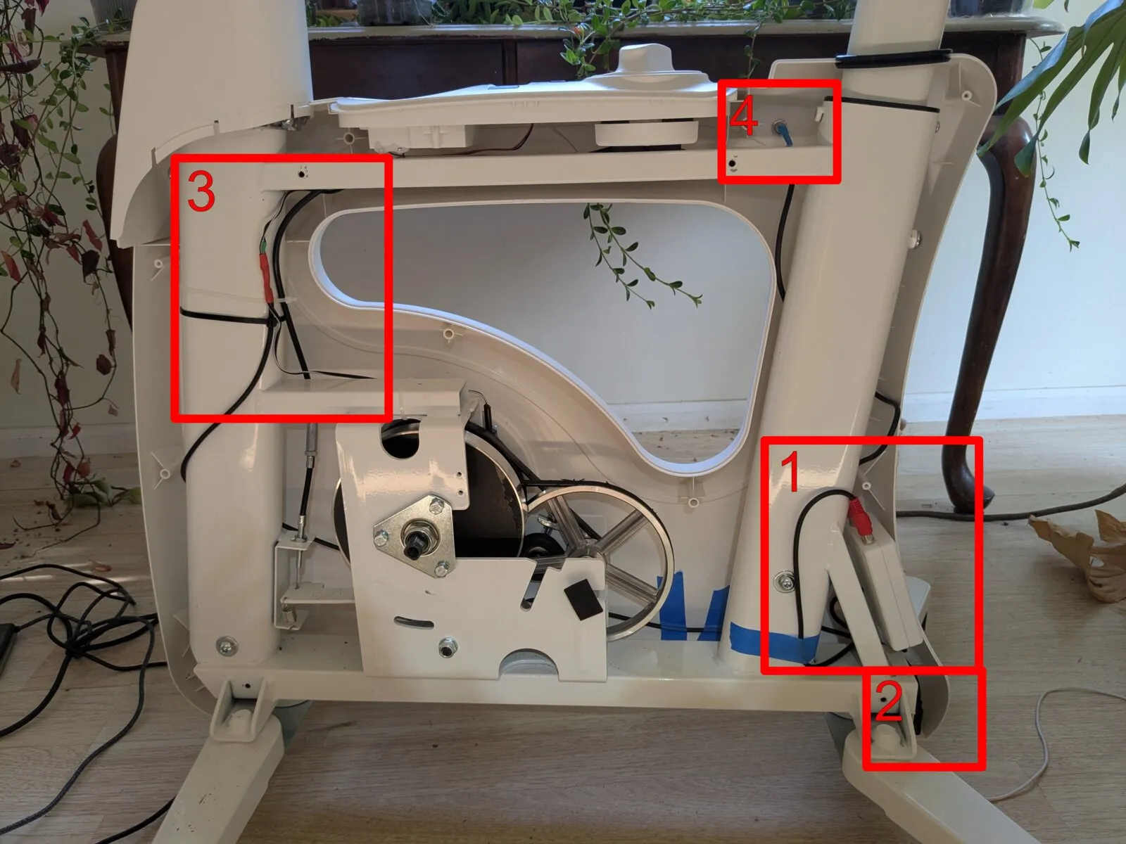
In order, we have 1. The ESP32, 2. A USB-C Power Connector, 3. A Patch Into The Reed Switch, and 4. An Indicator LED.
1. The ESP32
I used a (~$5) ESP32 devboard I got on Amazon: ESP32-S3-DevKitC-1-N16R8.
To house it, I used YAPP_Box to design and 3D print a little enclosure for it:
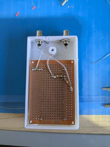
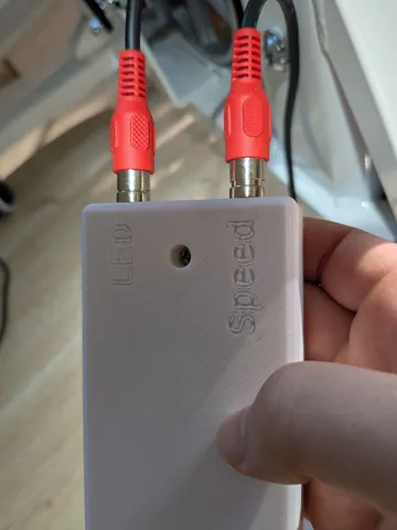
The RCA connectors and circuit on the protoboard are there to connect to the reed switch on the bike and the indicator LED I installed. (See sections 3 and 4 below). RCA connectors were just what I had lying around, I think on future projects I will prefer JST connectors.
2. A USB-C Power Connector
To relay USB-C power to the dev board, I got one of these panel mount USB-C extension cords ($5 on Amazon). I installed it at the base of the bike:
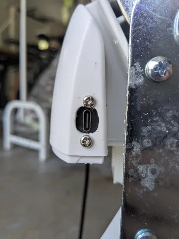
The connector works, but the plastic chassis of the bike was a little too thick for it, so it doesn’t work with wider USB-C connectors. For other projects I’ll probably look for other ways to panel-mount USB-C input.
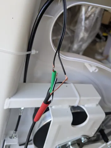
3. A Patch Into The Reed Switch
The line for the reed switch was easy to locate, and I spliced my own cable into it and then heat shrinked everything together. I kept it connected to the built-in LCD indicator on the bike, so that cadence and other info could still be displayed there. I handled level shifting with a few diodes / resistors that hooked up on the proto board in the microcontroller chassis.
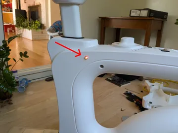
4. An Indicator LED
Finally, I drilled into the side of the bike to install a little indicator LED I could address in my code to indicate status or error conditions.
Putting It All Together
Before reassembling the bike, I flashed the ESP32 with the latest version of MicroPython and wrote a simple program to toggle the LED every time the reed switch was triggered:
from machine import Pin, Timer

led = Pin(4, Pin.OUT)
reed = Pin(5, Pin.IN, Pin.PULL_UP)

debounce_timer = Timer(0)
debouncing = False

def debounce_callback(t):
    global debouncing
    debouncing = False

def reed_irq_handler(pin):
    global debouncing
    if not debouncing:
        debouncing = True
        debounce_timer.init(mode=Timer.ONE_SHOT, period=50, callback=debounce_callback)
        led.value(not led.value())

reed.irq(trigger=Pin.IRQ_FALLING, handler=reed_irq_handler)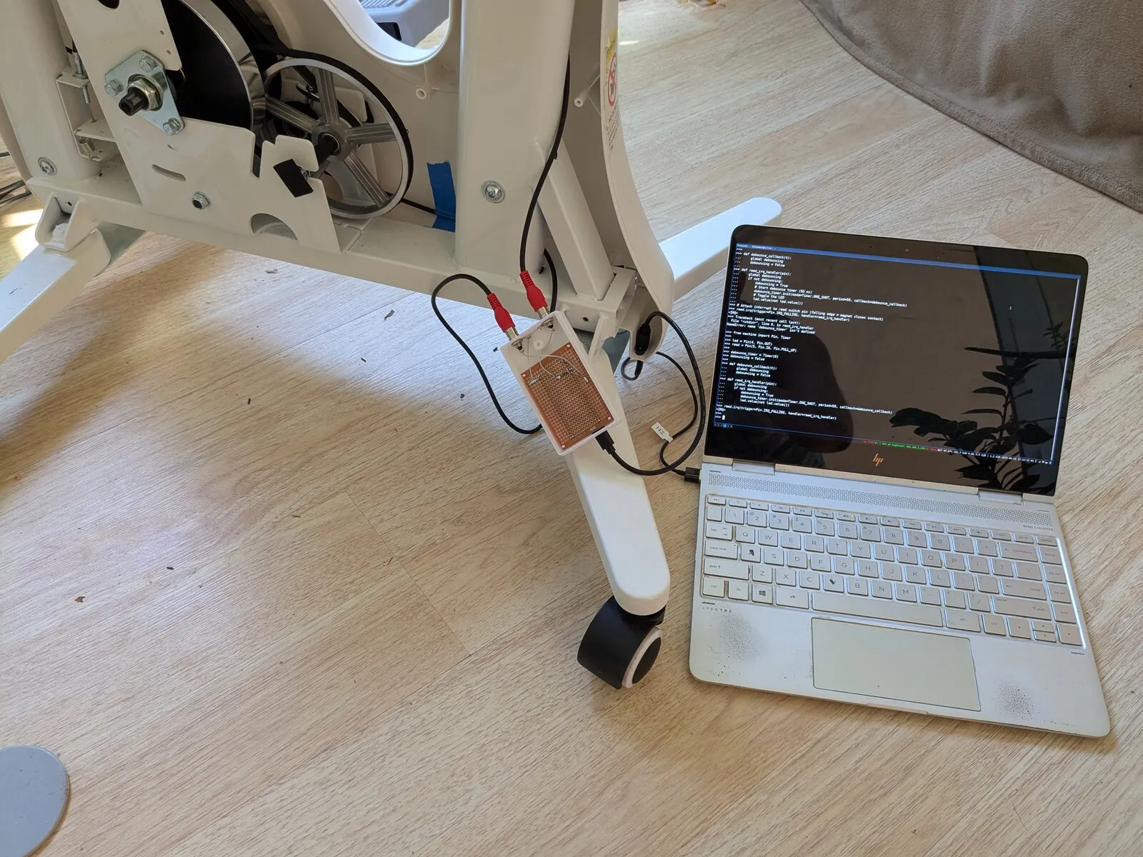
…it worked! Not bad for a little weekend project! Now to write a firmware to log my activity sessions, and an app to sync with Google Health Connect. I’ll talk about this in a future post.